Examples
Airfoil
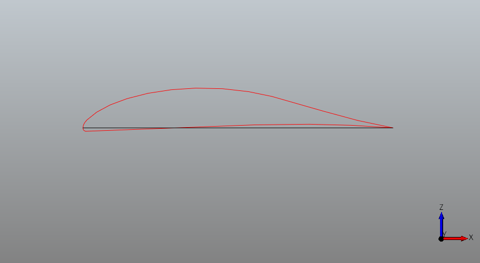
This example on building an airfoil NURBS curve with occ_airconics is included in the occ_airconics core Qt viewer examples.
First import the primitives module in which the Airfoil class is contained and the pythonocc-core Qt viewer:
from airconics import primitives
# Visualisation with Python-OCC (ensure plot windows are set to qt)
from OCC.Display.SimpleGui import init_display
display, start_display, add_menu, add_function_to_menu = init_display()
Next, define the inputs to Airfoil class. In this example, we’ll use the SeligProfile type airfoil, leading edge point in origin, unit chord along x axis, no rotation around the x or y axes.
Note: This class also supports construction of NACA 4 digit profiles using input keyword NACA4Profile. See Airfoil API reference.
LEPoint = [0., 0., 0.]
ChordLength = 1
Rotation = 0
Twist = 0
AirfoilSeligName = 'dae11'

# Instantiate class to set up a generic airfoil with these basic parameters
Af = primitives.Airfoil(LEPoint, ChordLength, Rotation, Twist,
                        SeligProfile=AirfoilSeligName)
Finally, display the curve and chord line
display.DisplayShape(Af.Curve, update=True)
display.DisplayShape(Af.ChordLine, update=True)
start_display()
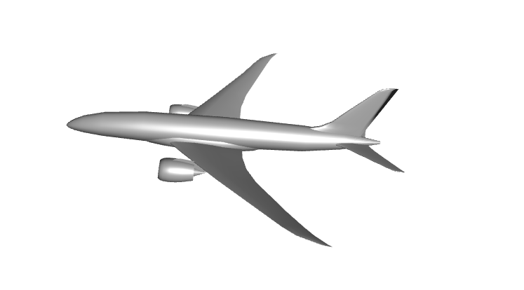
Transonic Airliner
In this example, the transonic airliner geometry example from the Rhinoceros Airconics plugin [1] is shown. All renderings are static images here, but represent interactive renderings when run as an IPython notebook available here. Interactive shapes can be viewed by clicking the shape hyperlinks however, as produced by the PythonOCC x3dom renderer.
For examples using the pythonocc-core Qt viewer, refer to the occ-airconics examples/core directory
from airconics import liftingsurface, engine, fuselage_oml
import airconics.AirCONICStools as act
from airconics.Addons.WebServer.TornadoWeb import TornadoWebRenderer
from IPython.display import display
Parameter Definitions
Parameters used here correspond to a geometry similar to that of the Boeing 787-8
Propulsion=1
EngineDia=2.9
FuselageScaling=[55.902, 55.902, 55.902]
WingScaleFactor=44.56
WingChordFactor=1.0
Topology=1
EngineSpanStation=0.31
EngineCtrBelowLE=0.3558
EngineCtrFwdOfLE=0.9837
Scarf_deg=3

# Derived Parameters
FuselageHeight = FuselageScaling[2]*0.105
FuselageLength = FuselageScaling[0]
FuselageWidth  = FuselageScaling[1]*0.106
WingApex = [0.1748*FuselageLength,0,-0.0523*FuselageHeight]
# Fin:
FinChordFact = 1.01
FinScaleFact = WingScaleFactor/2.032
# TailPlane
TPChordFact = 1.01
TPScaleFact = WingScaleFactor * 0.388
# Engine:
NacelleLength = 1.95*EngineDia
Wing, Transonic Airliner
Formulation of lifting surfaces in occ_airconics (and AirCONICS) follows the suggestions in Sobester [2] in which geometry–attached curvilinear functionals are used instead of parameters for shape definition. That is, \(G(\bf{f}, \bf{X})\), where
$$\qquad \textbf{f} = \left[ f_1(\textbf{X}_1), f_2(\textbf{X}_2), ... f_m(\textbf{X}_m)\right],$$ and
$$\textbf{X}_i = \left[x_1^i, x_2^i,...\right], \forall i = 1,...m$$
as opposed to the conventional \(G(\bf{X})\) formulation where the shape \(G\) changes in response to changes in design parameters \(\textbf{X}\). The functions \(f_i\) are defined by:
$$Sweep (\epsilon)$$
$$Chord (\epsilon)$$
$$Rotation (\epsilon)$$
$$Twist (\epsilon)$$
$$Airfoil (\epsilon)$$
where \(\epsilon\) represents the spanwise coordinate ranging from 0 at the root of the wing to 1 at the tip. Output of the airfoil function uses the airconics.primitives.Airfoil class here, which fits a NURBS curve to airfoil coordinates.
The following code demonstrates construction of a wing using built in examples for a transonic airliner wing and tailplane (below).
# Import all example functional definitions for the Common Research Model (CRM) Wing:
from airconics.examples.wing_example_transonic_airliner import *

# Position of the apex of the wing
P = WingApex

# Class definition
NSeg = 11
ChordFactor = 1
ScaleFactor = 50

# Generate (surface building is done during construction of the class)
Wing = liftingsurface.LiftingSurface(P, mySweepAngleFunctionAirliner,
                                        myDihedralFunctionAirliner,
                                        myTwistFunctionAirliner,
                                        myChordFunctionAirliner,
                                        myAirfoilFunctionAirliner,
                                        SegmentNo=NSeg,
                                        ScaleFactor=WingScaleFactor,
                                        ChordFactor=WingChordFactor)

# Evaluate the root chord:
RootChord = Wing.RootChord

# Display
renderer = TornadoWebRenderer()
Wing.Display(renderer)
display(renderer)
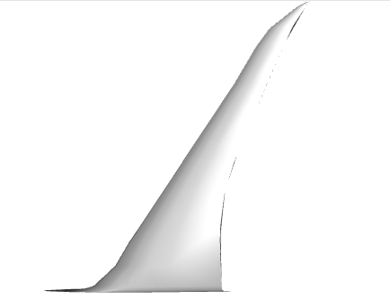
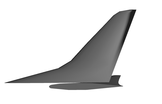
Tailplane, Transonic Airliner
The same Lifting Surface class is used here to generate the fin and tailplane of the aircraft, using a different set of input functionals (also defined in airconics.examples).
from OCC.gp import gp_Ax1, gp_Pnt, gp_Dir
from airconics.examples.tailplane_example_transonic_airliner import *

# Position of the apex of the fin
P = [36.98-0.49-0.02, 0.0, 2.395-0.141]

SegmentNo = 10

Fin = liftingsurface.LiftingSurface(P, mySweepAngleFunctionFin,
                                    myDihedralFunctionFin,
                                    myTwistFunctionFin,
                                    myChordFunctionFin,
                                    myAirfoilFunctionFin,
                                    SegmentNo=SegmentNo,
                                    ChordFactor=FinChordFact,
                                    ScaleFactor=FinScaleFact)

#    Create the rotation axis centered at the apex point in the x direction
RotAxis = gp_Ax1(gp_Pnt(*P), gp_Dir(1, 0, 0))


Fin.RotateComponents(RotAxis, 90)

# Position of the apex of the tailplane
P = [43, 0.000, 1.633+0.02]

SegmentNo = 100
ChordFactor = 1.01
ScaleFactor = 17.3

TP = liftingsurface.LiftingSurface(P, mySweepAngleFunctionTP,
                                   myDihedralFunctionTP,
                                   myTwistFunctionTP,
                                   myChordFunctionTP,
                                   myAirfoilFunctionTP,
                                   SegmentNo=SegmentNo,
                                   ChordFactor=TPChordFact,
                                   ScaleFactor=TPScaleFact)

# Display
renderer = TornadoWebRenderer()
Fin.Display(renderer)
TP.Display(renderer)
display(renderer)
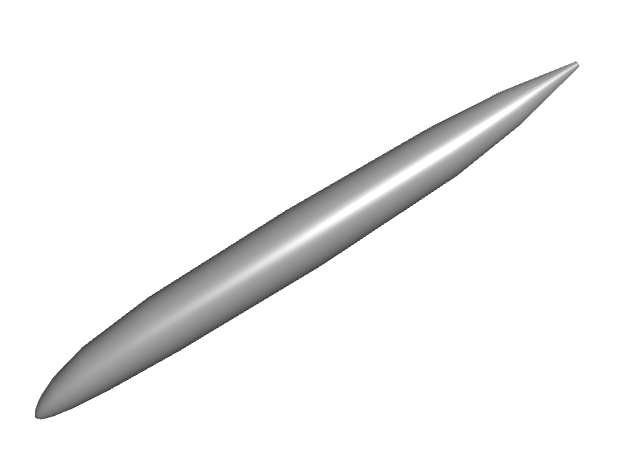
Fuselage Transonic Airliner
Fuselage shapes are created following the parameterisation used in Sobester [3]. That is, the outer mould line (OML) is split into a Nose, Central and Tail section, the length of which is described on input to Fuselage class as a percentage of the total length. Rib curves are then formed by fitting a NURBS curve to the intersection points of sectional planar cuts and the guide curves of the extremeties of the OML e.g. Port, top and bottom curves. The OML is fitted in occ_airconics using the Open CASCADE ThruSections loft.
NoseLengthRatio=0.182
TailLengthRatio=0.293

Fus = fuselage_oml.Fuselage(NoseLengthRatio, TailLengthRatio,
                            Scaling=FuselageScaling,
                            NoseCoordinates=[0., 0., 0],
                            CylindricalMidSection=False,
                            Maxi_attempt=5)

# Display
renderer = TornadoWebRenderer()
Fus.Display(renderer)
display(renderer)
('Surface fit attempt ', 1)
('Attempting thrusections surface fit with network density                setup ', array([35, 30, 15,  5, 20]))
Network surface fit succesful on attempt 1
Wing-Body Fairing:
The wing-body fairing is here created as a simple ellipsoid shape around the root section of the wing.
Note that this component will be displayed only in the final model.
# WingBodyFairing: A simple ellipsoid:
from airconics.base import AirconicsShape
WTBFZ = RootChord*0.009 #787: 0.2
WTBFheight = 1.8*0.1212*RootChord #787:2.7
WTBFwidth = 1.08*FuselageWidth
WTBFXCentre = WingApex[0] + RootChord/2.0 + RootChord*0.1297 # 787: 23.8
WTBFlength = 1.167*RootChord #787:26

WBF_shape = act.make_ellipsoid([WTBFXCentre, 0, WTBFZ], WTBFlength, WTBFwidth, WTBFheight)
WBF = AirconicsShape(components={'WBF': WBF_shape})
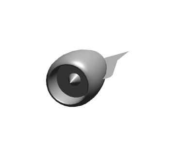
Engine + Pylon
First, obtain the wing section and chord at which the engine will be fitted, then fit then engine. The default inputs to the Engine class produce a turbofan engine with Nacelle similar to that of the RR Trent 1000 / GEnx and its pylon (currently a flat plate only).
from airconics import engine

EngineSection, Chord = act.CutSect(Wing['Surface'], EngineSpanStation)
CEP = Chord.EndPoint()
Centreloc = [CEP.X()-EngineCtrFwdOfLE*NacelleLength,
            CEP.Y(),
            CEP.Z()-EngineCtrBelowLE*NacelleLength]

eng =  engine.Engine(Chord,
                     CentreLocation=Centreloc,
                     ScarfAngle=Scarf_deg,
                     HighlightRadius=EngineDia/2.0,
                     MeanNacelleLength=NacelleLength)

# Display
renderer = TornadoWebRenderer()
eng.Display(renderer)
display(renderer)
Miscelaneous operations
# Trim the inboard section of the main wing:
CutCirc = act.make_circle3pt([0,WTBFwidth/4.,-45], [0,WTBFwidth/4.,45], [90,WTBFwidth/4.,0])
CutCircDisk = act.PlanarSurf(CutCirc)
Wing['Surface'] = act.TrimShapebyPlane(Wing['Surface'], CutCircDisk)

#Mirror the main wing and tailplane using class methods:
Wing2 = Wing.MirrorComponents(plane='xz')
TP2 = TP.MirrorComponents(plane='xz')
eng2 = eng.MirrorComponents(plane='xz')
can work? True
error status: - Ok
Note: MirrorComponents currently mirrors only the shape
components, other attributes will not be mirrored

Note: MirrorComponents currently mirrors only the shape
components, other attributes will not be mirrored

Note: MirrorComponents currently mirrors only the shape
components, other attributes will not be mirrored
Ipython Cell Renderer:
Now render the finished airliner model:
from airconics.Addons.WebServer import TornadoWeb
renderer = TornadoWeb.TornadoWebRenderer()
#    display all entities:
# Fuselage and wing-body fairing
Fus.Display(renderer)
WBF.Display(renderer)

# #The Wings:
Wing.Display(renderer)
Wing2.Display(renderer)

#The Tailplane:
TP.Display(renderer)
TP2.Display(renderer)

#The Fin:
Fin.Display(renderer)

#The Engines:
eng.Display(renderer)
eng2.Display(renderer)

# Finally show the renderer
display(renderer)
Topology model
This is a work in progress towards a topologically flexible model based on the tree-type definition described in Sobester [1]. Note the geometry is not currently defined by the tree however, the tree is simply stored as a result of adding components - this is for demonstration only, and the process is yet to be automated.
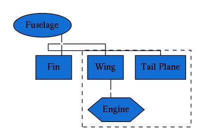
Transonic Airliner Topology
First, we’ll try to add the previously created transonic airliner components to a Topology, including the number of descendant nodes that will be attached to each, and then display the resulting tree graph. The LISP representation of this tree could be described as
Fuselage(Fin, Mirror[ (TailPlane, Wing(Engine))],
where opening brackets indicate that the following component is to be `atttached’ to the preceeding shape. Using the shorthand described in [1], this is equivalent to \(E(L, |L, L(P))\), where \(E\) is an enclosure/fuselage object, \(L\) is a lifting surface, \(|\) is a mirror plane and \(P\) is a propulsion unit [1]. Study the Airliner model above and recursively work through the components, starting from the fuselage, and think about the sub-components are attached to them to assert that this is true.
The \(xz\) mirror plane is included in this representation, between central objects (Fuselage, Fin) and the mirrored objects (Tail Plane, Wing, Engine). Notice that the dotted line box surrounds the entities that will be mirrored when Topology.Build() is called.
from airconics import Topology
from IPython.display import Image
import pydot
topo_renderer = TornadoWebRenderer()

topo = Topology()

# Note: no checks are done on the validity of the tree yet,
topo.AddPart(Fus, 'Fuselage', 3)
topo.AddPart(Fin, 'Fin', 0)

# Need to add a mirror plane here, arity zero
from OCC.gp import gp_Ax2, gp_Dir, gp_Pnt
xz_pln = gp_Ax2(gp_Pnt(0, 0, 0), gp_Dir(0, 1, 0))
topo.AddPart(xz_pln, 'Mirror', 0)

# These are the mirrored entities, with their arities
topo.AddPart(TP, 'Tail Plane', 0)
topo.AddPart(Wing, 'Wing', 1)
topo.AddPart(eng, 'Engine', 0)

# print the Topology (resembles a LISP tree)
print(topo)

# Create the graph with pydot
graph = pydot.graph_from_dot_data(topo.export_graphviz())
Image(graph.create_png())
Skipping geometry construction for Topology
E(L, |L, L(P))
# This line will mirror geometry 'under' (added after) the mirror plane
topo.Build()

topo.Display(topo_renderer)
display(topo_renderer)
<class 'OCC.gp.gp_Ax2'>
Note: MirrorComponents currently mirrors only the shape
components, other attributes will not be mirrored

Skipping geometry construction for AirconicsShape
<class 'OCC.gp.gp_Ax2'>
Note: MirrorComponents currently mirrors only the shape
components, other attributes will not be mirrored

Skipping geometry construction for AirconicsShape
<class 'OCC.gp.gp_Ax2'>
Note: MirrorComponents currently mirrors only the shape
components, other attributes will not be mirrored

Skipping geometry construction for AirconicsShape
Could not display shape type <class 'OCC.gp.gp_Ax2'>: skipping
Let’s try some further tests to the topology class representation using some other examples. For now, these are empty geometries, and inputs to the Fuselage, LiftingSurface and Engine classes are not yet included in the Topology tree.
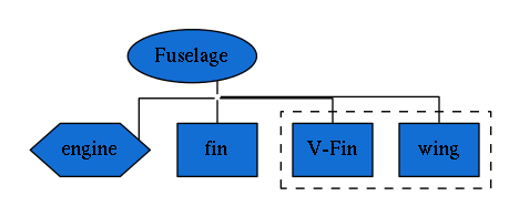
Predator UAV
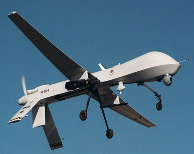 Photo source: US Air Force
# Setup
# Create mock components, without generating any geometry
fus = Fuselage(construct_geometry=False)
engine = Engine(construct_geometry=False)
fin = LiftingSurface(construct_geometry=False)
mirror_pln = gp_Ax2()
wing = LiftingSurface(construct_geometry=False)
Vfin = LiftingSurface(construct_geometry=False)

# For now we must manually add parts and affinities
topo = Topology()
topo.AddPart(fus, 'Fuselage', 4)
topo.AddPart(engine, 'engine', 0)
topo.AddPart(fin, 'fin', 0)
topo.AddPart(mirror_pln, 'mirror_pln', 0)
topo.AddPart(wing, 'wing', 0)
topo.AddPart(Vfin, 'V-Fin', 0)

print(topo)

graph = pydot.graph_from_dot_data(topo.export_graphviz())
Image(graph.create_png())
Skipping geometry construction for Fuselage
No HChord specified to fit engine to: creating default
Skipping geometry construction for Engine
Lifting Surface functional parameters not defined:
Initialising without geometry construction
Skipping geometry construction for LiftingSurface
Lifting Surface functional parameters not defined:
Initialising without geometry construction
Skipping geometry construction for LiftingSurface
Lifting Surface functional parameters not defined:
Initialising without geometry construction
Skipping geometry construction for LiftingSurface
Skipping geometry construction for Topology
E(P, L, |L, L)
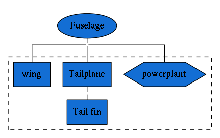
Fairchild Republic A-10 Thunderbolt
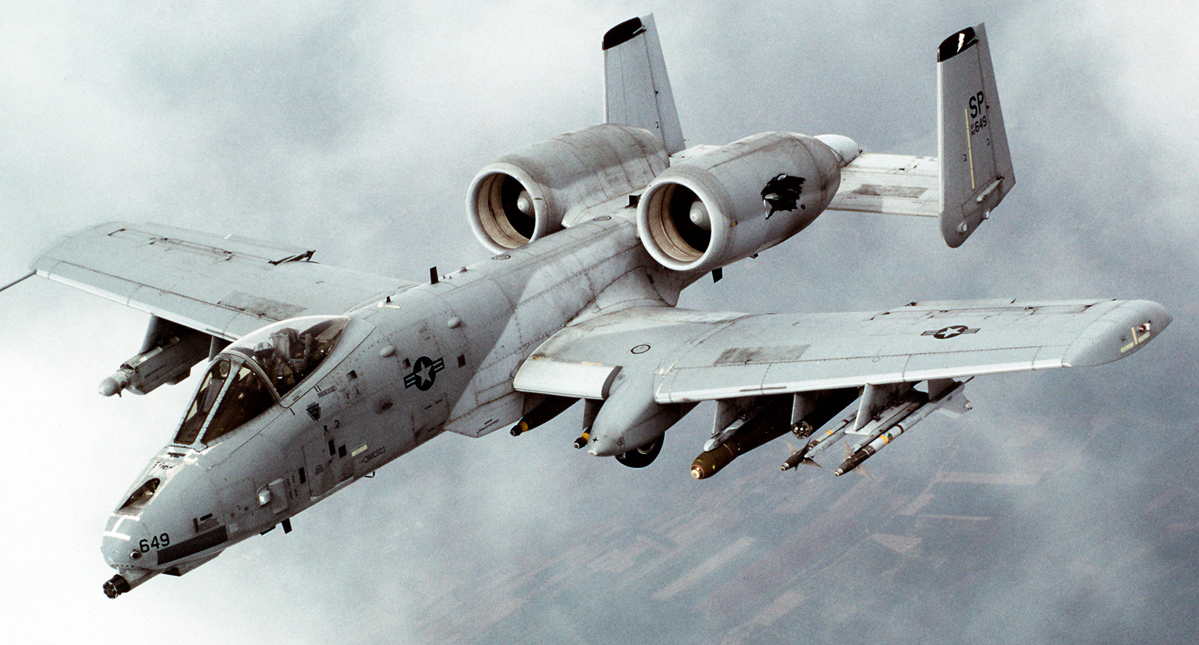 Photo source: Airman Magazine 1999
# Setup
# Create mock components, without generating any geometry
fus = Fuselage(construct_geometry=False)
mirror_pln = gp_Ax2()
engine = Engine(construct_geometry=False)
wing = LiftingSurface(construct_geometry=False)
tailplane = LiftingSurface(construct_geometry=False)
tail_fin = LiftingSurface(construct_geometry=False)

topo = Topology()
topo.AddPart(fus, 'Fuselage', 3)
topo.AddPart(mirror_pln, 'mirror', 0)
topo.AddPart(engine, 'powerplant', 0)
topo.AddPart(tailplane, 'Tailplane', 1)
topo.AddPart(tail_fin, "Tail fin", 0)
topo.AddPart(wing, "wing", 0)

print(topo)

graph = pydot.graph_from_dot_data(topo.export_graphviz())
Image(graph.create_png())
Skipping geometry construction for Fuselage
No HChord specified to fit engine to: creating default
Skipping geometry construction for Engine
Lifting Surface functional parameters not defined:
Initialising without geometry construction
Skipping geometry construction for LiftingSurface
Lifting Surface functional parameters not defined:
Initialising without geometry construction
Skipping geometry construction for LiftingSurface
Lifting Surface functional parameters not defined:
Initialising without geometry construction
Skipping geometry construction for LiftingSurface
Skipping geometry construction for Topology
E(|P, L(L), L)
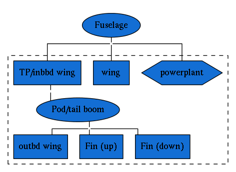
Scaled Composites Proteus
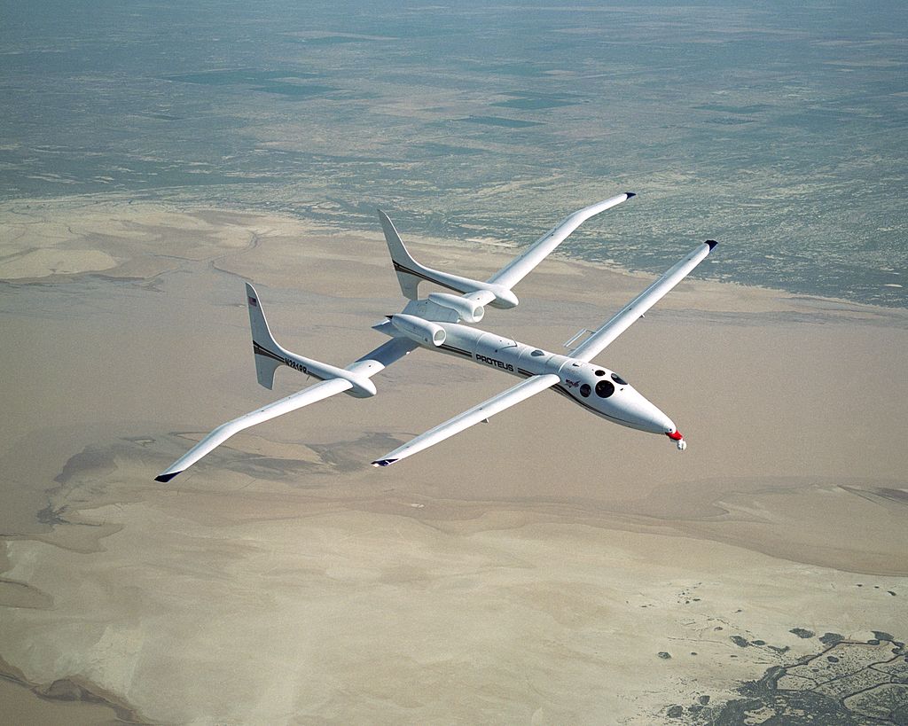 Photo source: NASA
# Setup
# Create mock components, without generating any geometry
fus = Fuselage(construct_geometry=False)
mirror_pln = gp_Ax2()
engine = Engine(construct_geometry=False)
wing_in = LiftingSurface(construct_geometry=False)
tailplane = LiftingSurface(construct_geometry=False)
pod = Fuselage(construct_geometry=False)
finup = LiftingSurface(construct_geometry=False)
findown = LiftingSurface(construct_geometry=False)
wing_out = LiftingSurface(construct_geometry=False)


topo = Topology()
topo.AddPart(fus, 'Fuselage', 3)
topo.AddPart(mirror_pln, 'mirror', 0)
topo.AddPart(engine, 'powerplant', 0)
topo.AddPart(wing, "wing", 0)
topo.AddPart(wing_in, "TP/inbbd wing", 1)
topo.AddPart(pod, 'Pod/tail boom', 3)
topo.AddPart(wing_out, "outbd wing", 0)
topo.AddPart(finup, "Fin (up)", 0)
topo.AddPart(findown, "Fin (down)", 0)

for node in topo._Tree:
    print(node)


graph = pydot.graph_from_dot_data(topo.export_graphviz())
Image(graph.create_png())
Skipping geometry construction for Fuselage
No HChord specified to fit engine to: creating default
Skipping geometry construction for Engine
Lifting Surface functional parameters not defined:
Initialising without geometry construction
Skipping geometry construction for LiftingSurface
Lifting Surface functional parameters not defined:
Initialising without geometry construction
Skipping geometry construction for LiftingSurface
Skipping geometry construction for Fuselage
Lifting Surface functional parameters not defined:
Initialising without geometry construction
Skipping geometry construction for LiftingSurface
Lifting Surface functional parameters not defined:
Initialising without geometry construction
Skipping geometry construction for LiftingSurface
Lifting Surface functional parameters not defined:
Initialising without geometry construction
Skipping geometry construction for LiftingSurface
Skipping geometry construction for Topology
(Fuselage, E, 3)
(mirror, |, 0)
(powerplant, P, 0)
(wing, L, 0)
(TP/inbbd wing, L, 1)
(Pod/tail boom, E, 3)
(outbd wing, L, 0)
(Fin (up), L, 0)
(Fin (down), L, 0)
References
[1] Sobester, A., “Four Suggestions for Better Parametric Geometries,” 10th AIAA Multidisciplinary Design Optimization Conference, AIAA SciTech, American Institute of Aeronautics and Astronautics, jan 2014.
[2] Sobester, A., “Self-Designing Parametric Geometries,” 56th AIAA/ASCE/AH- S/ASC Structures, Structural Dynamics, and Materials Conference, AIAA SciTech, American Institute of Aeronautics and Astronautics, jan 2015.